
Short answer
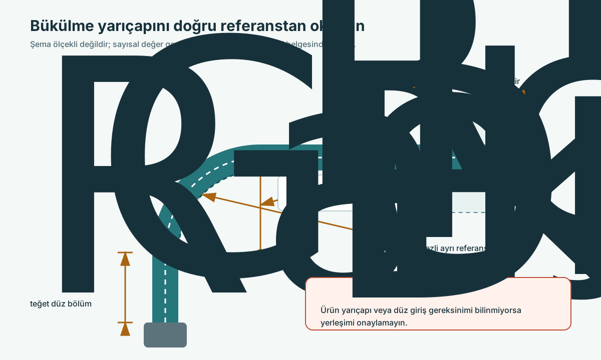
At the fitting exit, the straight section and bending conditions required by the manufacturer must be maintained rather than forcing the hose into a sharp turn immediately. The required length depends on the product family and the connection; a single fixed dimension must not be used for all hoses.
Technical explanation
The connection area does not behave in the same way as the free, flexible part of the hose. Bending concentrated near the end can combine with torsion or external loads. Manufacturer guides emphasize proper routing around the connection and maintaining the minimum radius. An elbow fitting or a suitable rigid pipe arrangement can improve some layouts; such changes are evaluated together with flow, support and maintenance access.
Topic-specific checkpoints
| Item | Description |
|---|---|
| Fitting area | Transition between rigid and flexible zones |
| Straight section | Product-specific installation requirement |
| Turn | Correct end angle and radius |
| Recheck | All movements of the new layout |
How to evaluate it in practice
For a line where damage keeps occurring at the base of the fitting, document it with photographs that represent not only the idle state but also safe operating positions. Mark the start point of the bend and any contact with the opposing surface. Match the straight section or installation note in the product catalog with the actual fitting. If space is insufficient, refer the end geometry or the machine connection to an engineering assessment instead of forcing the hose into a smaller radius. Repeat the rubbing and motion check for the new layout as well.
Original editorial recommendation; not a clause of a standard.
Frequently asked questions
Is damage at the base of the fitting always due to poor crimping?
No. In addition to assembly quality, incorrect routing, bending, torsion and external loads must also be investigated.
Source coverage
-
S017
Parker Safety Guide, Publication 4400-B.1 Parker Hannifin · accessed 2026-10-20 PDF page 3; 3.7 Minimum Bend Radius, 3.8 Twist Angle and Orientation and 3.13 RoutingPDF page 3; 3.7 Minimum Bend Radius and 3.13 RoutingPDF page 3; 3.1 Component Inspection, 3.2 Hose and Fitting Assembly and 3.3 Related Accessories | PDF page 2; 2.8 Routing, 2.10 Mechanical Loads and 2.11 Physical Damage
-
S024
Hose and Flexible Tubing, MS-01-180 Swagelok · accessed 2026-10-19 PDF pages 4–5 / printed 253–254: Nomenclature; pages 8–9: selection, installation and use
-
S031
Hydraulics in Action: Maximizing Hose Lifetime Continental · accessed 2026-10-19 Optimizing Hose Routing for Longevity