
Short answer
Hose length is not the shortest distance between two connections. It must be determined by evaluating together the end geometry, all positions of the motion, the minimum bend radius, the straight sections and the support arrangement.
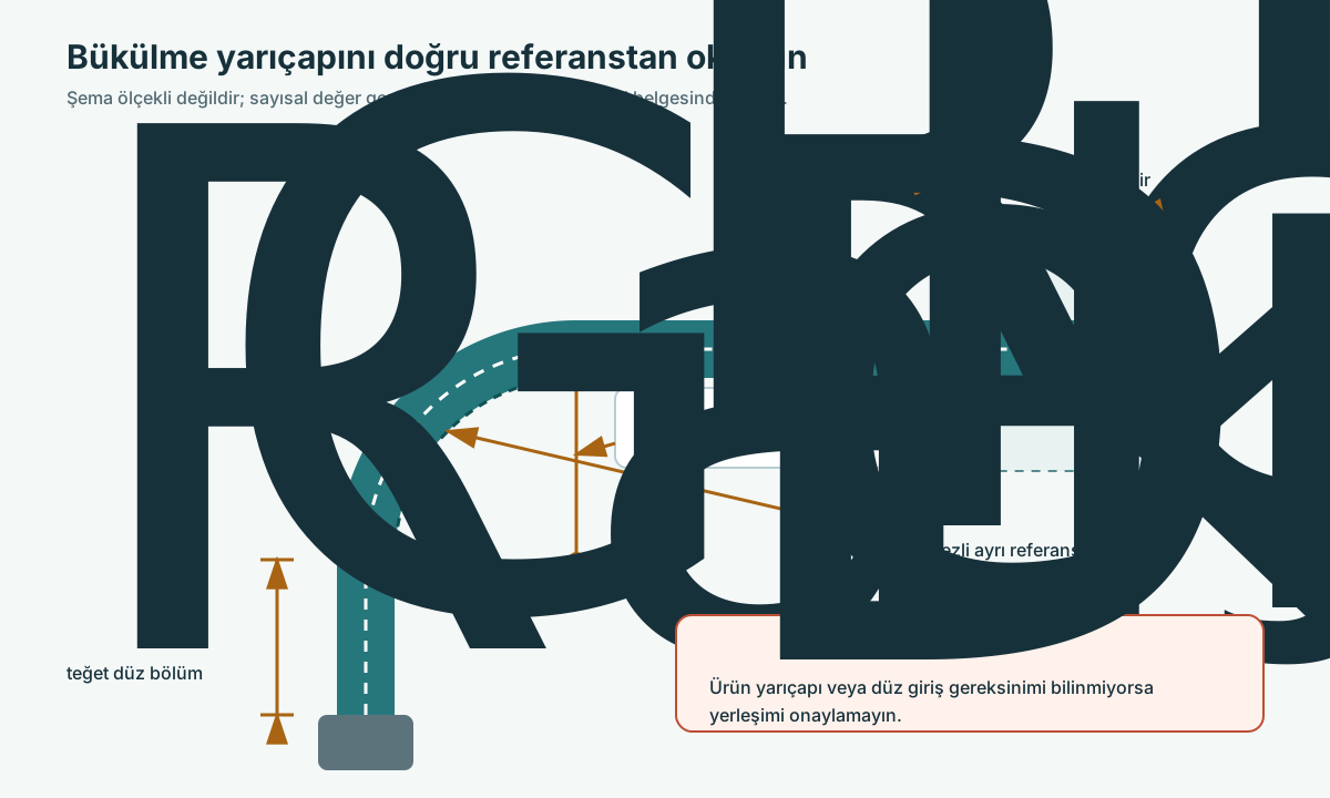
Technical explanation
A short assembly can cause tension or a sharp bend; an excessively long assembly can cause rubbing, sagging or snagging. In a moving application, the initial position alone is not sufficient. The manufacturer's length change and dynamic service conditions must be taken into account. Cut length and completed assembly length are different; the effective length contribution of the fittings is calculated separately. For this reason, the correct length cannot be found in all applications by adding a universal percentage.
Topic-specific checkpoints
| Item | Description |
|---|---|
| Distance | Connection reference surfaces |
| Motion | Routing in all positions |
| Geometry | Radius and straight sections |
| Length definition | Distinction between cut length and assembly length |
How to evaluate it in practice
Add the fully open, fully closed and critical intermediate positions to the routing drawing. Define the sealing or reference surfaces of the A/B ends. Mark hot surfaces, sharp edges and moving parts along the route. Check the manufacturer's radius on the drawing at true scale. If a sample is needed, carry out a safe motion check before final series production. Fix the accepted length and end orientation with a revision-controlled drawing; do not pass the field copy to the workshop as a verbal dimension.
Original editorial recommendation; not a clause of a standard.
Frequently asked questions
Can I add the same percentage allowance to every hose?
A general percentage is not suitable for all applications. Manufacturer and routing conditions must be used as the basis.
Source coverage
-
S017
Parker Safety Guide, Publication 4400-B.1 Parker Hannifin · accessed 2026-10-20 PDF page 3; 3.7 Minimum Bend Radius, 3.8 Twist Angle and Orientation and 3.13 Routing | PDF page 3; 3.1 Component Inspection, 3.2 Hose and Fitting Assembly and 3.3 Related Accessories | PDF page 2; 2.8 Routing, 2.10 Mechanical Loads and 2.11 Physical DamagePDF page 2; 2.8 Routing, 2.10 Mechanical Loads and 2.11 Physical DamagePDF page 2; 2.13 LengthPDF page 3; 3.1 Component Inspection, 3.2 Hose and Fitting Assembly and 3.3 Related Accessories | PDF page 2; 2.13 Length
-
S024
Hose and Flexible Tubing, MS-01-180 Swagelok · accessed 2026-10-19 PDF pages 4–5 / printed 253–254: Nomenclature; pages 8–9: selection, installation and use
-
S031
Hydraulics in Action: Maximizing Hose Lifetime Continental · accessed 2026-10-19 Optimizing Hose Routing for Longevity